Showing posts with label KG 13A. Show all posts

Tuesday, April 28, 2020

What's the difference between a KG 13A and a KG 13B

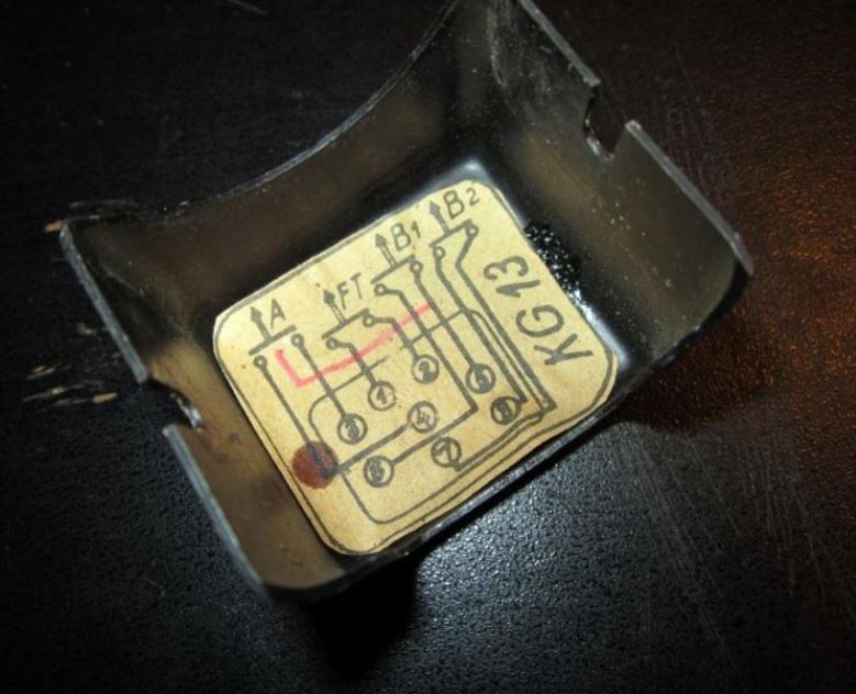
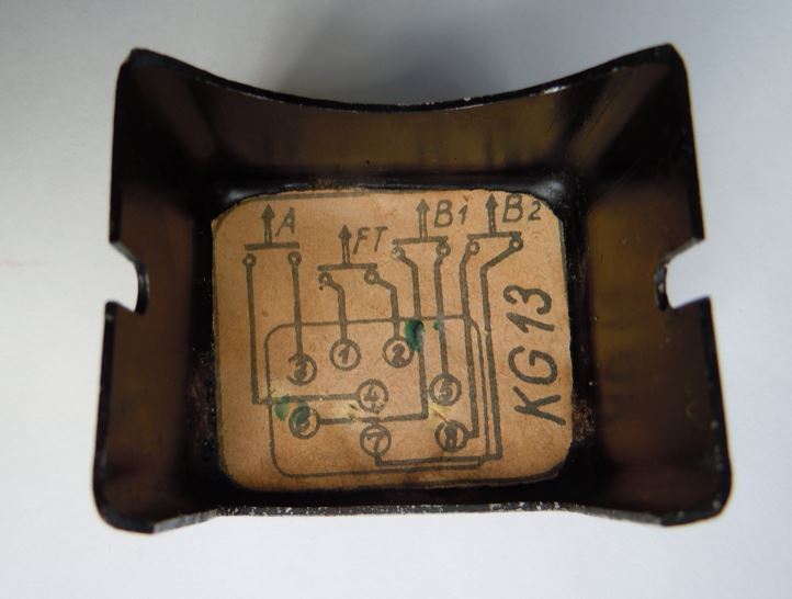
Long time since my last post. I recently got asked what the difference between the KG 13A and KG 13B was. Externally, both were identical (with the exception of some smaller details like data plates and casting features depending on the manufacturer). The difference was the internal wiring only. Let's have a look at the wiring diagram that was glued to the inside of the wiring cover. First a KG 13A:

3) KG 13A WIRING DIAGRAM


2) KG 13B WIRING DIAGRAM


3) KG 13A WIRING DIAGRAM (Used in a Fw 190 instead of a KG 13B)

The only difference is an additional connection from 5 to the A-button in the KG 13B compared to the KG 13A. The third example above was installed in a Fw 190. Fw 190s were usually fitted with KG 13Bs, but in this example the internal wiring of a KG 13A was modified to reflect the diagram of a B. 

The Bf 109 usually had a KG 13A (or C in very late war production aircraft) and the Fw 190 usually a KG 13B (or C in very late war production aircraft). But there were exceptions and both aircraft types are known to have used both KG 13As and Bs.

I hope this clarifies some questions. If you have any control stick for identification, I'd like to hear from you. Please contact me (via this blog or via my website www.vintageeagle.com).


Tuesday, April 12, 2011

Messerschmitt Bf 109 G-6/U4

CONTROL STICK:
The Bf 109 G-6/U4 used a KG 13A (Knüppelgriff 13A) control stick. It had the Fl-number Fl 47915 (Gerät-Nr. 102-288A). 

Wiring diagram August '43
ARMAMENT:
The Bf 109 G-6/U4 was equipped with two fuselage mounted MG 131 13mm machine guns and one engine mounted MK 108 30mm cannon. Rüstsatz R6 offered the possibility to add one MG 151 20mm cannon underneath each wing.

ELECTRICAL WIRING DIAGRAM:
The electrical wiring diagram code for the control stick was the same as for the standard Bf 109 G-6 (click here to go to the Bf 109 G-6 article): ‘V23’.

Image from the Bf 109 G-6/U4 manual (August '43)
While the MG 131s were automatically charged when the safety switch in the round counter control box SZKK3 (Schuss-, Zähl- und Kontrol-Kasten 3) was toggled, the MK 108 cannon had to be manually charged. However, after take off the MK 108 was already charged and manually charging was only necessary in case of a gun jams. According to the wartime manual (dated August 1943) the MK 108 was charged via a small switch (see 'e' in image on the left and 'P301' in the image above) that was attached to the instrument panel. At the time the manual was prepared, it was envisaged to replace the switch by a button. The manual did not state where this button was to be located, but it was most likely attached directly to the control stick like seen on later Bf 109 G-10s.

BUTTONS:
A factory delivered KG 13A had three buttons used for weapons and one radio button. The top trigger was called A-Knopf (Knopf = button), the top center button was called B-Knopf (or also B1-Knopf) and the top left button was called B2-Knopf. Depending on the equipment the aircraft carried, additional buttons could be attached to the KG 13A control stick or the wiring was adjusted. The buttons in the Bf 109 G-6/U4 were used as follows:

Bf 109 G-6/U4 without Rüstsatz R6 (two wing-mounted MG 151 cannons):
A-Knopf: 2x MG 131 (fuselage mounted)
B1-Knopf: 1x MK 108 (engine mounted)
B2-Knopf: drop ordnance

When the Rüstsatz R6 was installed, it was originally planned to fire the MK 108 and MG 131s via the A-button and the wing mounted MG 151 cannons via the B1-button. However, a later added note in the manual stated that based on combat experience, the MK 108 should be fired via the B1-button and the wing mounted MG 151s together with the fuselage mounted MG 131s via the A-button:

Original scheme: Bf 109 G-6 with Rüstsatz R6 (two wing-mounted MG 151 cannons):
A-Knopf: 2x MG 131 (fuselage mounted) and 1x MK 108 (engine mounted)
B1-Knopf: 2x MG 151 (in wing pods)
B2-Knopf: drop ordnance

Revised scheme: Bf 109 G-6 with Rüstsatz R6 (two wing-mounted MG 151 cannons):
A-Knopf: 2x MG 131 (fuselage mounted) and 2x MG 151 (in wing pods)
B1-Knopf: 1x MK 108 (engine mounted)
B2-Knopf: drop ordnance

SOURCES:
L. Dv. T. 2109 G-6/U4/Wa. "Bf 109 G-6/U4. Schusswaffenanlage. Bedienungsvorschrift/Wa. (Stand Juli 1943) Ausgabe August 1943."

Messerschmitt Bf 109 G-6

A KG 13A control stick in a Bf 109 G
This is my first post. The intention of this blog is to give readers more information about aircraft control sticks of the German Luftwaffe in WWII. There will be information both about the different control stick models in use as well as the specific application to certain aircraft models.

I start with the most common fighter plane of the German Luftwaffe, the Messerschmitt Bf 109 G-6. 

CONTROL STICK:
The Bf 109 G-6 used a KG 13A (Knüppelgriff 13A). It had the Fl-number Fl 47915 (Gerät-Nr. 102-288A). 

ARMAMENT:
The Bf 109 G-6was equipped with two fuselage mounted MG 131 13mm machine guns and one engine mounted MG 151 20mm cannon. Rüstsatz R6 offered the possibility to add one MG 151 20mm cannon underneath each wing.

ELECTRICAL WIRING DIAGRAM:
Each device that was connected to the electrical circuit received a code consisting of a letter, that designated the type of equipment, and a number. The control stick in the Bf 109 G-6 received the code ‘V23’. This code was usually either applied by hand or by decal onto the control stick and it was unique to the Bf 109 G. Hence, a control stick that has a ‘V23’ designation came from a Bf 109 G. The top left button had the code ‘R25’.
Electrical wiring diagram of the Bf 109 G-6 KG13A.
The Bf 109 G-6 was equipped with an engine mounted MG 151 20mm cannon and two fuselage mounted MG 131 13mm machine guns. All weapons were automatically charged when the safety switch in the round counter and control box SZKK3 (Schuss-, Zähl- und Kontrol-Kasten 3) in the upper instrument panel was turned on. 

BUTTONS:
A factory delivered KG 13A had three buttons used for weapons and one radio button. The top trigger was called A-Knopf (Knopf = button), the top center button was called B-Knopf (or also B1-Knopf) and the top left button was called B2-Knopf. Depending on the equipment the aircraft carried, additional buttons could be attached to the KG 13A control stick or the wiring was adjusted. The buttons in the Bf 109 G-6 were used as follows:

A snapshot from the manual of the Bf 109 G-6 showing the top of the KG 13A

Bf 109 G-6 without Rüstsatz R6 (two wing-mounted MG 151 cannons):
A-Knopf: 2x MG 131 (fuselage mounted)
B1-Knopf: 1x MG 151 (engine mounted)
B2-Knopf: drop ordnance

Bf 109 G-6 with Rüstsatz R6 (two wing-mounted MG 151 cannons):
A-Knopf: 2x MG 131 (fuselage mounted) and 1x MG 151 (engine mounted)
B1-Knopf: 2x MG 151 (in wing pods)
B2-Knopf: drop ordnance

SOURCES:
L. Dv. T. 2109 G-5 und G-6/Wa "Bf 109 G-5 und G-6. Schusswaffenanlage. Bedienungsvorschrift/Wa. (Stand März 1943) Ausgabe April 1943."

The cockpit of a Swiss Messerschmitt Bf 109 G-6