CONTROL STICK:
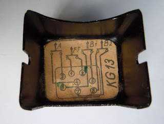
The Focke Wulf Fw 190 G-3 used a KG 13B (Knüppelgriff 13B) control stick. It had the Fl-number Fl 47945 (Gerät-Nr. 102-288B).
ARMAMENT:
The Fw 190 G-3 was based in principle on the Fw 190 A-6, which was equipped with two fuselage mounted MG 17 7.92mm machine guns, two MG 151 20mm cannons in the wing roots and two wing mounted MG 151 20mm cannons. In the Fw 190 G-3, however, all except the two MG 151 cannons in the wing roots were usually not installed as the bomb load, and additional fuel carried in drop tanks underneath each wing made a weight reduction necessary.
 |
| Cockpit of Fw 190 G-3, W.Nr. 160016 (source: LIFE) |
The photo on the left shows the cockpit of Fw 190 G-3, W.Nr. 160016, St.Kz. DN+FP, that was captured and later test flown in the USA. Several things are worth noticing. First, note that instead of a round counter and control box 4 (Schuss-, Zähl- und Kontrollkasten 4, SZKK 4) with 4 separate round counters, only two round counters are installed in a SZKK 2 for the two MG 151 in the wing roots at the top of the panel. Hence, the aircraft was indeed only equipped with two MG 151 cannons.
Many (if not all?) Fw 190 G-3 were equipped with a simple one-axis autopilot that allowed automatic rudder control which could be used to maintain a straight path in a dive when dive bombing. While on later aircraft equipped with singe-axis autopilots, the switch for the course correction was usually integrated into the top of the control stick, it was not in this Fw 190 G-3. Instead, the switch was moved into the auxiliary panel just above the ZSK 244 box. The autopilot could be turned on or off via a simple toggle switch and a rotating wheel allowed course corrections to the left or right. Interestingly, another type of course input instrument (so-called ‘Richtungsgeber’) also with an on/off switch can be seen in the photo at the bottom left. It is not clear which (or if both) of the two course input instruments were used together with the single-axis autopilot (and what the purpose of the other was).
Note also that the control stick is missing its data plate and features a metal stripe at the base of the stick that was fitted to hold the wires coming from the stick in place. This was a typical feature seen only on Fw 190 sticks.
ELECTRICAL WIRING DIAGRAM:
 |
| 'V60' & MG 151 label on a Fw 190 KG 13B |
The electrical wiring diagram code for the control stick was ‘V60’, which was not unique to the Fw 190 G-3, but to most Fw 190 subtypes.
BUTTONS:
A factory delivered KG 13B had three buttons used for weapons and one radio button. The top trigger was called A-Knopf (Knopf = button), the top center button was called B-Knopf (or also B1-Knopf) and the top left button was called B2-Knopf. Depending on the equipment the aircraft carried, additional buttons could be attached to the KG 13B control stick or the wiring was adjusted. The buttons in the Fw 190 G-3 were used as follows:
Fw 190 G-3 (two wing-root-mounted MG 151 cannons):
A-Knopf: 2x MG 151 (wing-root mounted), [only if installed: 2x MG 17 (fuselage mounted)]
B1-Knopf: [only if installed: 2x MG 151 cannons (wing mounted)]
B2-Knopf: drop ordnance
 |
| KG 13B of Fw 190 G-3, W.Nr. 160016 (source: LIFE) |
|
 |
| Another photo showing the cockpit of Fw 190 G-3, W.Nr. 160016 (source: LIFE) |


